
RISAFloor is capable of providing analysis, code checks, and member optimization for Composite Beams. In RISAFloor a Composite Beam is defined as a hot rolled 'I' section beam with Composite Deck attached to its top flange. Composite behavior is achieved by steel studs which are welded to the top flange of the beam, and which project/embed into the concrete deck. The design of these beams may be performed based on the following codes:
Note:
The construction process of composite beam structures consists of the following steps:
If no shoring is provided under the beam during construction then the steel beam itself (without composite action) is required to support all of the following loads simultaneously, prior to the concrete hardening and reaching its design strength:
During this Pre-Composite phase the bending moment due to the loads listed above is compared against the beam's bending moment capacity according to AISC 360 Chapter F.
If shoring will be provided during construction this must be specified as a property of the deck. Beams which are placed under Shored Deck are not checked for Pre-Composite design, as it is assumed that the shoring will resist the Pre-Composite loads.
The results for pre-composite design are reported in the Member Detail Report under the Non Composite Bending section:
Note:
Regardless of whether shoring was used during construction, the composite section resists the post-construction design loads, as defined in the Load Combinations. These include all load categories which can be defined in RISAFloor except Const DL and Const LL.
During the model solution the program determines the required number and placement of studs, such that the beam's bending capacity as calculated according to AISC 360 Chapter I is sufficient to handle the bending moment due to Post-Composite loads.
The results for composite design are reported in the Member Detail Report under the Composite Bending section:
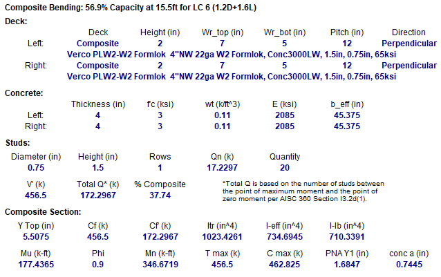
This section displays the deck type that controlled on each side of the beam, along with the deck properties as defined in the Deck Definitions.
This section displays concrete properties of the controlling deck as well as the calculated effective width for each side of the beam.
This section displays the stud properties of the controlling deck, along with following calculated values:
Note:
This section displays the information used to calculate the composite properties and is very useful for comparison to hand calculations. Items that are reported include:
The distance from the Elastic Neutral Axis to the extreme top concrete fiber, YTop.
The Compressive force in the concrete flange required to achieve full composite behavior, Cf, along with the actual flange compression force, Cf'. For ASD 9th Edition, these values are reported as Vh and Vh'.
The full transformed moment of inertia, Itr, as if the beam were fully composite, along with the effected moment of inertia based on the fact that the beam is only partially composite, Ieff.
The Distance from the Plastic Neutral Axis to the top of the steel section, PNA Y1.
The moment demand, Mu and the nominal moment capacity, Mn.
The depth of the effective compression block, a in the concrete versus the compression capacity of the full concrete slab, Cmax.
The tension capacity of the full steel section in yield, Tmax.
You can specify composite beams with uniform or segmented stud distributions using the Model Settings. Both methods of stud distribution will satisfy both the minimum stud spacing and the required composite action due to the moments in the beam. These moments include both the maximum moments in the beam for each load combination and the moments at concentrated load locations.
Note
Uniform Studs – When a uniform stud distribution is used, the program will calculate the maximum stud density required in the beam and apply that stud density to the entire beam.
Segmented Studs – When a segmented stud distribution is allowed, the program first fills the segments at the ends of the beam. The studs in these segments see a greater percentage of the total shear than the studs towards the mid-span of the beam.
The program will use the fewest number of stud rows possible. Once the number of studs in a segment reaches the number that can be fit into one row, the program will begin to add studs to the next beam segment. This continues until all the beam segments resisting the applied moment are filled. If necessary another row of studs will be added, starting again with the outer segments.
Note
RISAFloor allows different composite decks on either side of a beam. The slab properties are "left" and "right" where the beam is oriented such that its start point is at the bottom and its end point is at the top. When there are multiple decks on one side of a beam span, the program finds the deck with the most conservative design properties for each side of the beam. This will be based on the deck orientation (parallel or perpendicular), the thickness of the slab, the elastic modulus of the concrete, and the distance from beam flange to slab centroid. Since perpendicular decks receive no additional stiffness from the concrete filled ribs and control stud placement, they are always assumed to control over parallel ones.
Note:
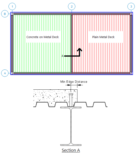
If the deck on one side of the beam is not a Composite Deck, then the effective deck width is taken as zero for that side of the beam. If the overhang distance of a diaphragm edge or opening edge is zero with respect to the beam centerline then the effective deck width is taken as zero in the direction of the opening or diaphragm edge. Therefore the program is assuming that the actual constructed detail provides sufficient side cover for the studs to allow composite action as an "L" beam.
In the Detail below, the Min Edge Distance shown must meet the requirements of AISC 360-10, Section I8.2d. It is the engineer's responsibility to ensure this edge distance is met when actually constructed.
The effective width is calculated for each side of the composite beam, and will be the lesser of one-eighth of the beam span, one-half of the distance to an adjacent support (a parallel beam or wall), or the distance to the diaphragm edge. In addition, there are two Model Settings settings that help determine the way that the effective width is determined.
The first setting is the Effective Width End Offset which allows you to ignore elements at the end of the beam.
End Off Set Example 1 - In looking at Beam A in the following figure, the opening beneath the beam does not limit its effective width if it falls within this end offset distance.
End Off Set Example 2 - In looking at Beam B, the effective width beneath Beam B is half the distance between points P2 and P4. This is because point P2 is the offset distance from the end of Beam B, and point P4 is the point on beam A normal to beam B at the offset distance.
The second parameter used to control effective width calculations is the Orthogonal Beam Angle which lets you define what angle constitutes orthogonal framing and therefore does not encroach on the effective width. In the figure above, Beam A and Beam C truly are orthogonal and therefore have no affect on each other’s effective widths. Beam B, however, is skewed to its supports and may or may not be considered orthogonal. For example, if the Orthogonal Beam Angle is set to 45 degrees then the Beam B – Beam C connection, which forms a 60 degree angle, is considered orthogonal. However, the Beam B – Beam A connection forms a 30 degree angle and therefore is not considered orthogonal and effective width calculations will not be performed there (i.e. the effective width above Beam A is zero). If you would like to override this effective width calculation you may do so by entering a value in the B-eff Left or B-eff Right columns on the Hot Rolled tab of the Beams spreadsheet.
Depending on the design code chosen, composite beams are defined having an equivalent elastic moment of inertia of the form:

Where Qn and Cf represent the total strength of the anchors vs the strength required to achieve 100% composite behavior. Unfortunately, tests have shown that composite beams typically exhibit an effective short term stiffness that is 15% to 30% lower than this value. For this reason RISAFloor has introduced a user defined factor on the equivalent elastic moment of inertia (entered on the Composite tab of the Global Model Settings) to reduce this value. This reduction is used on all composite beams regardless of which code was used to design them. Therefore, if this reduction is not desired, it should be set to 100%.
For the AISC codes (other than the 9th Edition ASD) , the program will use the LARGER value of either this reduced I-Effective, or I-Lower Bound (described below). For the 9th edition ASD the program will use the reduced effective moment of inertia directly and will not consider any potential I-Lower Bound increase.
For the Canadian Codes the program uses the reduction factor times the equivalent I given in the CSA code (which is slightly different than the formula given above) and does not consider I-Lower Bound.
No direct consideration is given to long term effects such as creep.
A lower bound moment of inertia is defined in the AISC commentary that may be used as an alternate to the reduced effective moment of inertia above. Refer to the AISC Specification and Commentary for more information on this formula.

This lower bound moment of inertia will be used if it is larger than the reduced effective moment of inertia. But, it will NOT be used if the design code is Canadian or AISC ASD 9th edition.
The total beam deflection is a summation of the pre-composite deflection (minus beam camber) and the post composite deflection. The pre-composite deflection is based on the unfactored pre-composite loads and the non-composite beam properties. The post composite deflection is based on the additional post composite loads and the composite beam properties.
Beams are cambered to reduce a portion of the pre-composite dead load deflection of the beam. This camber value may be entered directly on the Beams spreadsheet, or can be designed by the program based on the Camber rules in the Member Design Rules spreadsheet.
Negative Moments - All beams with negative moments will be designed as non-composite beams. Typically these will be continuous beams and cantilevers.
Beams with Slender Webs – Beams that have slender webs will be designed as non-composite beams.
Long Term Deflections – No calculations are performed to account for additional deflections due to the creep or shrinkage of the concrete slab.
Neutral Axis within Slab - RISAFloor assumes that the entire concrete slab will be on the compression side of the neutral axis. When the neutral axis is within the slab, the program does NOT adjust the composite section properties to neglect the portion of the concrete slab that is in tension.
For the calculation of the shear capacity of a single stud, longitudinal stud spacing (s) is assumed to be the greater of the 6 times the stud diameter or the value of min spacing given in the Model Settings. Refer to CSA S16-09, Clause 17.7.2.3(b).
No provision is given in the code for when deck rib height (hd) is not equal to 75 mm or 38 mm. For cases where hd is not equal to one of those values, the qrr value will be interpolated between the two formulas. Refer to CSA S16-09, Clause 17.7.2.4 for more information.
Refer to CSA S16-09, Clause 17.7.2.4 for more information.
There are number of different code checks that are required for composite ASD beams in the 9th Edition Specification. Unfortunately, that specification is not clear on what they are. An excellent explanation of this procedure is given in Steel Structures: Design and Behavior by Salmon & Johnson (1990, Harper Collins Publishers).
Note
The first check looks at the sum of pre and post-composite stresses. The pre-composite stresses use the section modulus, S, of the steel beam by itself and the pre-composite loading. The post -composite stresses use the effective section modulus, Seff, of the composite section and the post-composite loading. These stresses are listed as fby (sum of actual stresses) and Fby (allowable stress) on the detail report. Generally, Fby is 0.90*Fy.
fby = M(pre-composite) / S + {M(post-composte)} / Seff
This check is based on the following sentences from the ASD specification: "For composite beams constructed without temporary shoring, stresses in the steel section shall not exceed 0.9Fy. Stresses shall be computed assuming the steel section alone resists all loads applied before the concrete has reached 75% of its required strength and the effective composite section resists all loads applied after that time."
The second check looks at the sum of pre and post-composite loads against the full composite section. These stresses are listed as Fb and fb on the detail report. Generally, Fb is 0.66*Fy.
fb = Total Moment / Seff
This check is based on the following sentences from the ASD specification: "When shear connectors are used in accordance with Section I4, the composite section shall be proportioned to support all of the loads without exceeding the allowable stress prescribed in Section F1.1, even when the steel section is not shored during construction."
The third check looks at the concrete stresses for the post-composite loads ONLY. These are the fc and Fc values shown on the detail report. Generally, Fc is 0.45*f`c.
fc = M(post-composite) / (Itr / ytop * Es/Ec)
This check is based on the following sentences from the ASD specification: "The actual section modulus of the transformed composite section shall be used in calculating the concrete flexural compression stress and, for construction without temporary shores, this stress shall be based upon loading applied AFTER the concrete has reached 75% of its required strength. The stress in the concrete shall not exceed 0.45f`c."
Remember, it is possible for a composite beam to be designed as non-composite. This can occur for a number of reasons as described below.
Frequently, a beam member may be designated as composite, but the final design will end up being non-composite. There are still a number of reasons why this may happen.